3D Geometry, UV Mapping, and the Technical Limits of AI-Generated Meshes in 2026
ELI5
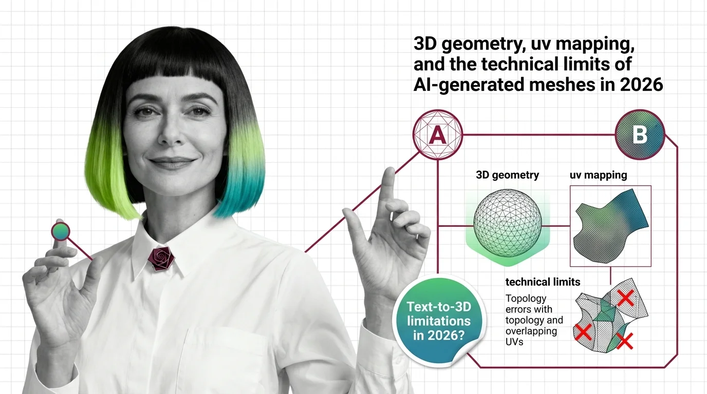
Text-to-3D converts a text prompt into a 3D mesh using AI. Mesh topology, UV mapping, and output format determine whether that mesh works in a game engine, 3D printer, or film pipeline — not just whether it looks good.
The preview renders flawlessly. The slicer crashes. The game engine refuses the import.
These three events, triggered in sequence by the same file, point to the same structural gap: a mesh that satisfies visual plausibility without satisfying geometric correctness. Text-to-3D tools are optimized for the former. Most production pipelines demand the latter. Closing that gap requires a vocabulary that most developers reaching for AI generation tools haven’t had reason to build yet.
The Vocabulary That Makes Failure Legible
Three-dimensional geometry is not a visual format. It is a mathematical structure with strict constraints — constraints that downstream tools enforce without mercy and that AI generators frequently violate without warning.
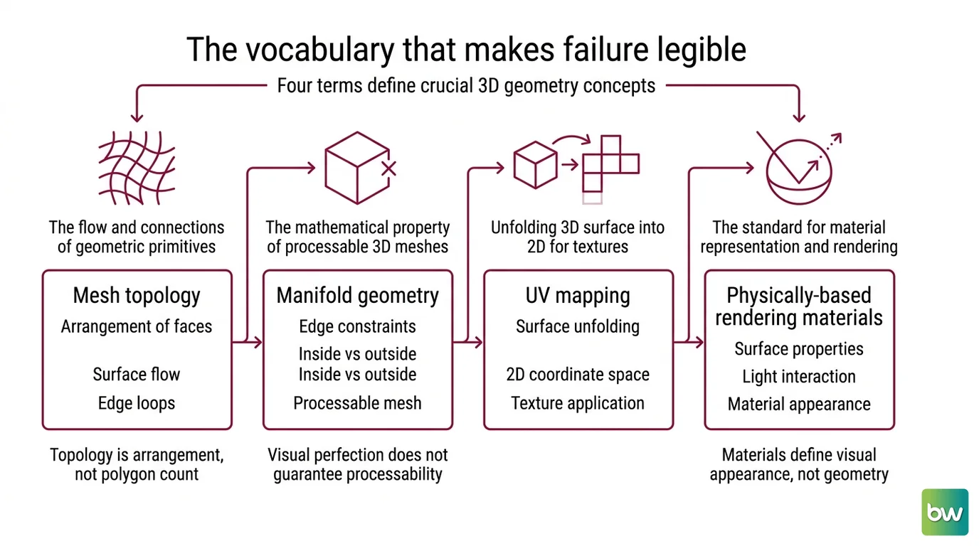
Four terms carry almost all the weight: mesh topology, UV mapping, physically-based rendering materials, and manifold geometry. Understanding what each term means explains not just why failures happen, but which kind of failure you’re looking at.
What 3D modeling concepts do you need to know before using text-to-3D tools?
A mesh is a collection of vertices (points in 3D space), edges (connections between vertices), and faces (polygons that tile the object’s surface). Every surface in a game engine, 3D printer slicer, or film renderer is, at some level, this arrangement of geometric primitives. The visual output is a consequence of how these primitives are arranged; the arrangement itself is what tools operate on.
Mesh Topology describes the arrangement of faces relative to each other — how they flow across the surface, where they meet at poles, whether they form loops that follow the object’s underlying structure. Two meshes of identical polygon count can have radically different topologies: one suitable for animation, one useless for it.
Topology is arrangement, not polygon count.
Manifold geometry is the mathematical property that determines whether a mesh is processable at all: every edge must be shared by exactly two faces. Where three or more faces share one edge, the surface becomes topologically ambiguous — the mesh is “non-manifold.” Slicers cannot determine what is inside versus outside a non-manifold object. Physics engines produce undefined collision behavior. A visually perfect mesh that fails the manifold test is, from a pipeline’s perspective, garbage.
UV Mapping unfolds the 3D surface into a 2D coordinate space so that flat texture images can be applied to it. Think of cutting a hollow 3D object along deliberate seams and flattening it — the resulting 2D layout is the UV map, and the pieces are UV islands. Where islands overlap, textures compete. Where they are distorted by poor unfolding, textures stretch or compress in ways that immediately read as broken.
PBR Materials extend UV mapping into a layered system: albedo (base color), normal (surface microdetail), roughness, metallic, ambient occlusion, and several others all reference the same UV space simultaneously. A broken UV map doesn’t break one texture channel — it breaks all of them at once, across every material property the surface carries.
This vocabulary is not background context. It is the prerequisite for understanding why AI generators fail in the specific ways they do.
What Your Export Actually Contains
The format a text-to-3D tool offers is not a file extension preference. It is a declaration of what the data structure contains — and what downstream pipeline can consume it. Choosing the wrong format doesn’t degrade quality; it fundamentally changes what operations are available to you.
Current tools export in four to seven formats depending on the product. The format names are familiar to most developers. Their actual data contracts are less obvious.
What output formats do text-to-3D tools support: OBJ, GLB, FBX, or splat files?
OBJ is the oldest format in active use — a text-based standard from the 1990s that stores vertex positions, UV coordinates, and face indices. It carries no animation, no skeletal rigging, and no native physically-based rendering support. The material data lives in a separate .mtl file, with textures in additional image files, making a minimum of three files for the simplest shaded object.
FBX is the industry standard for characters that move. It preserves skeletal hierarchies, vertex weights, blend shapes, and PBR material data, which is why Unity, Unreal, Maya, and 3ds Max all treat it as a first-class import format. If you’re generating a character for downstream rigging and animation, FBX is the format to request. Meshy and Tripo both export it.
GLB packages the mesh, PBR materials, and textures into a single binary file. It supports Draco mesh compression and targets web and real-time pipelines — load it in a browser or in a game engine’s asset pipeline without manual texture wrangling. Meshy exports seven formats in total: FBX, OBJ, GLB, USDZ, STL, BLEND, and 3MF (Meshy Docs). Tripo3D exports four: GLB, FBX, OBJ, and USDZ (Tripo3D Blog).
Gaussian Splat files (.splat, .ply, .spz) break more assumptions than any other format in this space. Gaussian Splatting represents a scene not as a mesh but as a collection of 3D Gaussians — oriented ellipsoids with learned color and opacity. Real-time rendering quality is high; the files achieve smooth frame rates in dedicated viewers.
A Gaussian Splat is not a geometry format.
It cannot be imported into a slicer, rigged, used as physics collision geometry, or treated as an editable surface. OpenUSD officially added Gaussian Splatting support in April 2026 (The Future 3D), integrating splat scenes into Unreal, NVIDIA Omniverse, and Houdini — but as radiance data, not editable geometry. The splat format ecosystem is not yet standardized: .splat, .ply, and the compressed .spz variant are all in use, with inconsistent tooling support. Tripo3D does not export any Gaussian Splat format; splat capture and export require specialized tools.
| Format | Single file | Animation | 3D-printable | Web-native |
|---|---|---|---|---|
| OBJ | No | No | Yes | Needs conversion |
| FBX | Yes | Yes (full) | Yes | No |
| GLB | Yes | Yes (limited) | Yes | Yes |
| Splat/PLY | Yes | No | No | Viewers only |
Note on Shap-E: OpenAI’s Shap-E is still referenced in tooling comparisons and tutorials. The repository has had no maintenance activity since 2023 and carries unresolved open issues (OpenAI GitHub). Treat it as an archived research release rather than a production option.
The Three Structural Gaps
Visual plausibility and geometric correctness are not the same property, and 2D diffusion models are trained to optimize for the former. The limitations that follow are structural — consequences of how these architectures process 3D problems, not implementation details to be resolved in the next version.
Three failure modes define the current generation landscape.
What are the technical limitations of text-to-3D models in 2026: topology errors, UV unwrapping, and multi-view consistency?
Topology errors. Generation pipelines produce what practitioners describe as “dense, chaotic triangle soups with UVs” (Tripo3D Blog) — meshes with far more faces than needed, irregular polygon distribution, and frequent non-manifold edges. For 3D printing, non-manifold edges mean the slicer cannot determine surface boundaries and rejects the file. For game engines, they produce undefined physics behavior. Meshy reports a 97% slicer pass rate across tested figurine models (Meshy Blog) — which is meaningful progress — but slicer acceptance measures whether the file is processable, not whether the topology is suitable for artistic editing or further modification.
UV unwrapping failures. Generating UV coordinates requires deciding where to place seams — the cuts in the 3D surface that allow it to unfold into 2D without excessive overlap or distortion. These decisions involve aesthetic judgment, pipeline conventions, and functional requirements that vary by downstream tool. Current generators produce UV coordinates that are technically present but practically unusable: overlapping islands, extreme distortion on curved surfaces, or seams placed across prominently visible geometry.
Research accepted to SIGGRAPH 2026 describes SATO (Strips-as-Tokens), an autoregressive framework that generates meshes with native UV segmentation rather than UV maps applied as a post-processing step (Quasa.io). Early results show meaningful improvement over standard AI UV output, but the paper acknowledges remaining stretching artifacts and suboptimal seam placement. SATO is a research contribution scheduled for publication, not yet a shipping feature in any production tool.
Multi-view consistency. Multiview Diffusion approaches address a structural problem: text-to-image diffusion models have no latent 3D representation. They generate each viewpoint of an object from 2D pattern distributions. When a model generates the front and back of the same object independently, the geometry each view implies may not be consistent — producing the “Janus problem,” where a head acquires two full front faces, one visible from each viewing angle.
NeRF-based approaches addressed this through volumetric 3D reconstruction: the Score Distillation Sampling method (introduced by Poole et al., 2022; DreamFusion project page) optimized a NeRF representation by iteratively rendering from random viewpoints and minimizing loss via a pretrained 2D diffusion model, building 3D coherence through the optimization process rather than assuming it. In production tooling as of 2026, faster feed-forward architectures have largely superseded SDS — Tripo3D’s Smart Mesh P1.0 generates structured meshes in approximately two seconds (Tripo3D Blog) — but the consistency problem SDS was designed to address has not disappeared; it has been reduced.
As the ConsDreamer paper acknowledges, “generated multi-view images often lack the exact consistency needed for unified 3D models” (arXiv). Methods like ConsDreamer and RecDreamer improve cross-view consistency; they do not eliminate the gap. Multi-view consistency remains an active research constraint, not a solved feature.
Multi-view consistency is unsolved, not just unoptimized.
Image-to-3D pipelines offer one practical workaround: generate a reference image with a known front orientation first, then lift it to 3D via an image-conditioned model. Single-view conditioning constrains the generator to maintain front-face coherence, reducing but not eliminating cross-view artifacts. The trade-off is that single-view conditioning limits geometric prediction for occluded surfaces; the back of an object is often extrapolated from texture patterns rather than geometric understanding.
What the Geometry Predicts
These three limitations combine in predictable ways. Understanding them as constraints lets you engineer around them before the import fails rather than after.
If you need a 3D-printable asset: request GLB or OBJ export, then verify manifold geometry in your slicer before committing to a print run. Visual quality in the tool’s preview is not a proxy for slicer acceptance. A high slicer pass rate means the geometry is processable — not that it is suitable for editing or modification after printing.
If you need a rigged character: FBX is the correct format, but plan for cleanup. AI-generated meshes rarely produce edge loops suitable for joint binding without artist revision. The skeleton will require manual binding, and topology that doesn’t follow anatomical structure makes weight painting significantly more labor-intensive.
If you need photorealistic real-time rendering and can accept a non-editable output: Gaussian Splatting delivers visual fidelity without the geometric constraints, and OpenUSD support in April 2026 substantially expanded pipeline integration options. Accept that you cannot edit, rig, or 3D-print the result.
Topology quality determines edit-path cost, not just render quality.
The implication for UV failures is less intuitive: even after topology cleanup, a broken UV map means texture work must be redone from scratch. A UV map is not a visual artifact that can be approximated — it is a coordinate system that the entire material pipeline references. A broken one on a complex asset can consume more artist-hours than the generation saved.
When it breaks: Non-manifold topology and broken UV unwrapping are the two failure modes that automated repair tools address least reliably; both typically require artist intervention, and the cost of that intervention scales with geometric complexity in ways that neither the generation tool nor its preview surface can estimate in advance.
The Data Says
Text-to-3D outputs in 2026 require production cleanup: the bottleneck is topology and UV quality, not texture resolution. Format selection is categorical — a Gaussian Splat cannot substitute for a mesh, and the choice determines what downstream operations are available. Multi-view consistency is an active research constraint, not a solved feature, and understanding this before generating determines whether you plan for cleanup or discover the need for it.
AI-assisted content, human-reviewed. Images AI-generated. Editorial Standards · Our Editors